COMPONENTS AND MATERIALS OF AUTOMOBILES ENGINES:
1) Cam Shafts:
Camshaft is a type of rotating device or apparatus used in
piston engines for propelling or operating poppet valves. Camshaft comprises of
series of cams that regulates the opening and closing of valves in the piston
engines. The camshaft works with the help of a belt, chain and gears.

2) Crankshaft:
Crankshaft is a device, which converts the up and down movement of the piston into rotatory motion. This shaft is presented at the bottom of an engine and its main function is to rotate the pistons in a circular motion. Crankshaft is further connected to flywheel, clutch, main shaft of the transmission, torque converter and belt pulley.
To convert Reciprocating motion of the Piston into Rotary motion, the Crankshaft and Connecting Rod combination is used. The Crankshaft which is made by Steel Forging or Casting is held on the Axis around which it rotates, by the Main Bearings, which is fit round the main Journals provided.
There are always at least two such bearings,one at the rare end and other at front end.the increase in number of Main Bearings for a given size of the Crankshaft means less possibility of Vibration and Distortion.
But it will also increase the diffculty of correct alignment in addition to increased production cost. The Main Bearings are mounted on the Crankcase of the Engine. The Balance weight or Counter weight keep the system in perfect balance.
The Crank Webs are extended and enlarged on the side of Journal opposite the Crank Throw so as to from balance weights. The Crankshaft may be made from Carbon Steel, Nickel Chrome or other Alloy Steel.
Connecting rods are made of metals, which are used, for joining a rotating wheel to a reciprocating shaft. More precisely, connecting rods also referred to as con rod are used for conjoining the piston to the crankshaft.
The load on the piston due to
combustion of fuel in the
combustion chamber is transmitted to crankshaft through the connecting rod.One end of connecting rod known as small end and is connected to the piston through gudgeon pin while the other end known as big end and is connected to crankshaft through
crank pin.
Connecting rods are usually made up of drop forged I section.In large size
internal combustion engine,the connecting rods of rectangular section have been employed.In such cases,the larger dimensions are kept in the plane of rotation.
In
petrol engine,the connecting rod's big end is generally split to enable its clamping around the crankshaft.Suitable diameter holes are provided to accommodate connecting rod bolts for clamping.The big end of connecting rod is clamped with crankshaft with the help of connecting rod bolt,nut and split pin or
cotter pin.
Generally,plain carbon steel is used as material to manufacture connecting rod but where low weight is most important factor,aluminium alloys are most suitable.Nickel alloy steel are also used for heavy duty engine's connecting rod.
Connecting rods can be made of steel, aluminum, titanium, iron and other types of metals.
A crankcase is a metallic cover that holds together the crankshaft and its attachments. It is the largest cavity within an engine that protects the crankshaft, connecting rods and other components from foreign objects. Automotive crankcases are filled with air and oil, while Magnesium, Cast Iron, Aluminum and alloys are some common materials used to make crankcases.
Cylinder heads refers to a detachable plate, which is used for covering the closed end of a cylinder assembled in an automotive engine. It comprises of combustion chamber valve train and spark plugs. Different types of automobiles have different engine configurations such as Straight engine has only one cylinder head while a engine has two cylinder heads.

Engine belts are the bands made of flexible material used for connecting or joining two rotating shafts or pulleys together. These belts work in coordination with wheels and axles for transferring energy. When the wheels or shafts are positioned at extremely different angles, then the engine belts have the ability to change the direction of a force. Engine pulley is a type of machine or a wheel having either a broad rim or groomed rim attached to a rope or chain for lifting heavy objects

Oil is one of the necessities of an automobile engine. Oil is distributed under strong pressure to all other moving parts of an engine with the help of an oil pump. This oil pump is placed at the bottom of an engine in the oil pan and is joined by a gear to either the crankshaft or the camshaft. Near the oil pump, there is an oil pressure sensor, which sends information about the status of oil to a warning light or meter gauge.
The different parts of engine oil systems include:
a) Engine Oil
b) Engine Oil Cooler
c) Engine Oil Filter
d) Engine Oil Gaskets
e) Engine Oil Pan
f) Engine Oil Pipe
Automobile engine valves are devices that regulate the flow of air and fuel mixture into the cylinder and assist in expelling exhaust gases after fuel combustion. They are indispensable to the system of coordinated opening and closing of valves, known as valve train. Engine valves are made from varied materials such as Structural Ceramics, Steels, Superalloys and Titanium alloys. Valve materials are selected based on the temperatures and pressures the valves are to endure.
The primary components of engine valve are:
a) Inlet Valve
b) Exhaust Valve
c) Combination Valve
d) Check Valve
e) EGR Valve
f) Thermostat Valve
g) Overhead Valve
h) Valve Guide
i) Schrader Valve
j) Vaccum Delay Parts
Inlet Valve & Exhaust Valve-
Function-Inlet valve allow the fresh charge of air-fuel mixture to enter the cylinder bore.Exhaust valve permits the
burnt gases to escape from the cylinder bore at proper timing.

An engine block is a metal casting that serves as a basic structure on which other engine parts are installed. A typical block contains bores for pistons, pumps or other devices to be attached to it. Even engines are sometimes classified as small-block or big-block based on the distance between cylinder bores of engine blocks. Engine blocks are made from different materials including Aluminum alloys, gray cast iron, ferrous alloys, white iron, gray iron, ductile iron, malleable iron, etc.
An engine pulley is a wheel with a groove around its circumference, upon which engine belts run and transmit mechanical power, torque and speed across different shafts of an engine. An engine houses pulley units of different sizes for cam shaft drive, accessory drive and timing belts. Molded plastics, iron and steel are normally used to make engine pulleys.
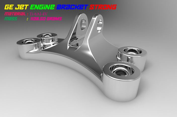
An engine bracket is a metallic part used to join an engine mount to the power unit or the body of a vehicle. These auto parts are installed between a vehicle's body and power unit to dampen the vibrations generated by the engine, thus preventing a vehicle's body from shaking due to the vibrations. Engine brackets are made from Ductile Iron Cast, Aluminum, Polypropylene, Fiberglass and alloys.
Automotive mounting bolts secure different automobile components viz. air bags, brake fittings, etc. on to a supporting structure. Likewise, engine mounting bolts help secure an automobile's engine in place. Based on usage, a number of materials such as alloys, silicon bronze, bronze, ceramic, carbon, aluminum, nylon, phosphor bronze, nickel silver, plastic, titanium, zirconium and stainless steel are utilized to produce these bolts.

Piston is a cylindrical plug which is used for moving up and down the cylinder according to the position of the crankshaft in its rotation. Piston has multiple uses and functions. In the case of four-stroke engine the piston is pulled or pushed with the help of crankshaft while in the case of compression stroke, piston is pushed with the powerful explosion of mixture of air and fuel.
Piston comprises of several components namely:
a) Piston Pins
b) Piston Floor Mat
c) Piston Rings
d) Piston Valve
14) Piston rings:
Piston rings provide a sliding seal between the outer edge of the piston and the inner edge of the cylinder. The rings serve two purposes:
· They prevent the fuel/air mixture and exhaust in the combustion chamber from leaking into the sump during compression and combustion.
· They keep oil in the sump from leaking into the combustion area, where it would be burned and lost.

Push rods are thin metallic tubes with rounded ends that move through the holes within a cylinder block and head, to actuate the rocker arms. Pushrods are found in valve-in-head type engines and are essential for the motion of engine valves. Some commonly used materials for manufacturing pushrods are Titanium, Aluminum, Chrome Moly and Tempered Chrome Moly.
16) Valve train:
Valve train consists of various components and parts, which enables valves to operate and function smoothly. Valve train comprises of three main components: camshafts, several components which are used for turning the camshaft’s rotating movement into reciprocating movement, and lastly valves and its various parts.
The primary components of valve train are:
a) Tappet
b) Rocker Arms
c) Valve Timing System
17) Governor
It controls the speed of engine at a different load by regulating fuel supply in diesel engine. In petrol engine, supplying the mixture of air-petrol and controlling the speed at various load condition.
18) Carburetor
It converts petrol in fine spray and mixes with air in proper ratio as per requirement of the engine.
19) Fuel Pump
This device supplies the petrol to the carburettor sucking from the fuel tank.
20) Spark Plug
This device is used in petrol engine only and ignite the charge of fuel for combustion.
21) Fuel Injector
This device is used in diesel engine only and delivers fuel in fine spray under pressure.
22) Gudgeon Pin
Connects the piston with small end of connecting rod.
This pin connects the piston with small end of the connecting rod,and also known as piston pin.It is made up of case hardened steel and accurately ground to the required diameters.Gudgeon pins are made hollow to reduce its weight,resulting low inertia effect of reciprocating parts.
This pin is also known as "Fully Floating" as this is free to turn or oscillate both in the piston bosses as well as the small end of the connecting rod.There are very less chances of seizure in this case but the end movement of the pin must be restricted to score the cylinder walls.This can be achieved by using any one of the following three methods,
A) One spring circlip at each end is fitted into the groove in the piston bosses.
B) On spring circlip is provided in the middle.
C) Bronze or Aluminium pads are fitted at both ends of the pin,which prevents the cylinder walls from being damaged.
The gudgeon pin may also be semi-floating type,in which either the pin is free to turn or oscillate in the small end bearing but secured in the piston bosses or it may secured in the small end bearing and allowed a free oscillating movement in the piston bosses.This method provides more bearing area at the bosses and hence no need for providing bushes there in,is preferred.
23) Crank Pin
Hand over the power and motion to the
crank shaft which come from piston through connecting rod.
24) Sump
The sump surrounds the crankshaft. It contains some amount of oil, which collects in the bottom of the sump (the oil pan).
25) Distributor –
It operates the ignition coil making it spark at exactly the right moment. It also distributes the spark to the right cylinder and at the right time. If the timing is off by a fraction then the engine won't run properly.
HOPE YOU HAVE LEARNED A BIT . . . . . . ..
IF ANY COMMENTS OR QUERIES MAIL HERE